DIY Quadrature Encoder
A quadrature encoder I hacked together for a personal project 02 Jan 2011
A quadrature encoder I hacked together for a personal project 02 Jan 2011
Here is a circuit diagram for a quadrature encoder I made for a recent project using two phototransistors.

Schmitt triggers filter the output and adjustments can be made with the three potentiometers. One is used for adjusting the LED current and the others are for adjusting tuning the sensitivity of each phototransistor. Here is the finished board.
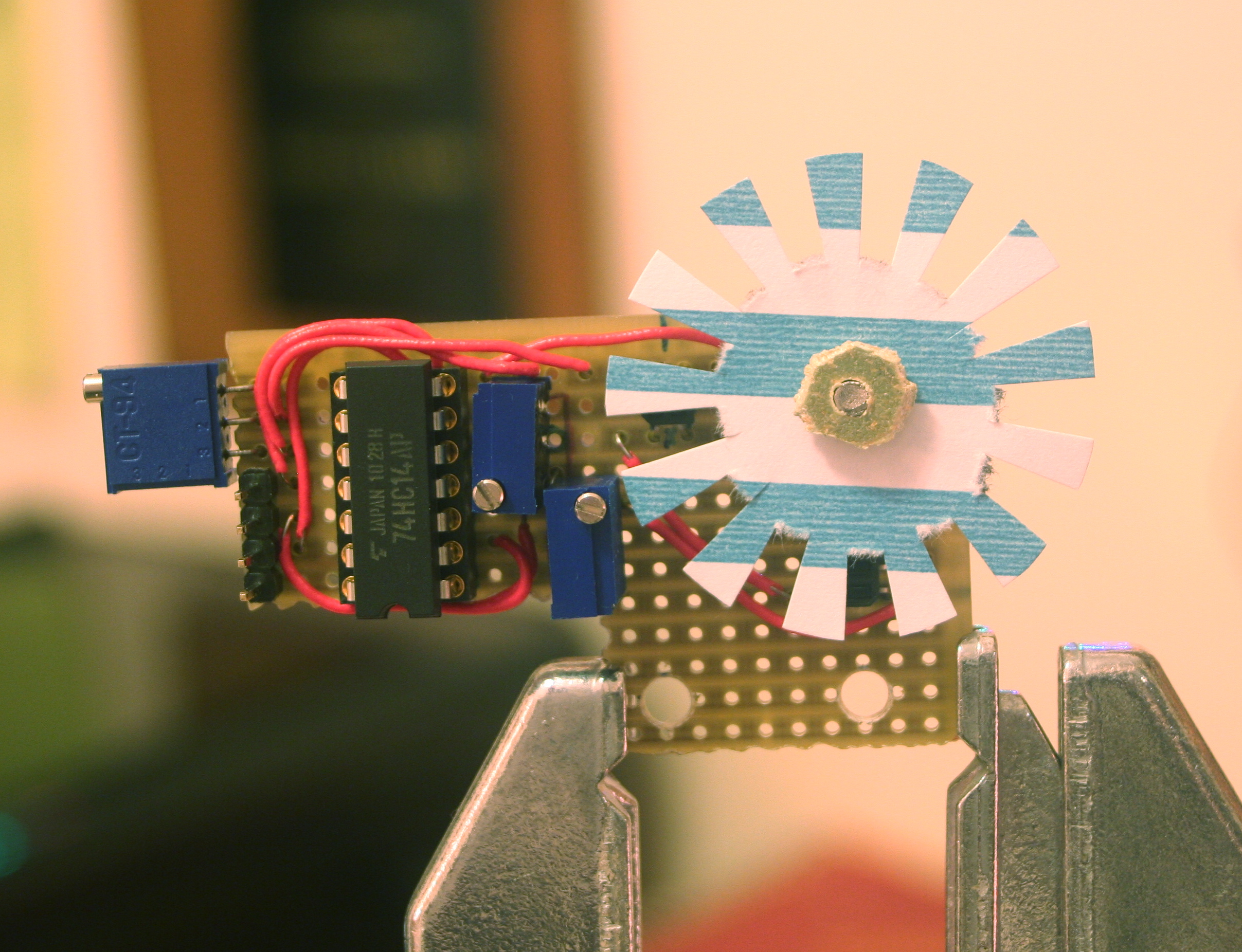
I notches out of an index card because it ended up working better than a black and white pattern on the card. Here is a diagram I made planning the circuit board.

##How it Works
A quadrature encoder works by measuring two square wave signals which are ninety degrees out of phase and advance as the wheel turns. These two signals are generated by the two photointerruptors.
It is called a quadrature encoder because the two signals are always in one of four states.

By detecting the transitions between states, we can detect clockwise and counterclockwise steps.
